Original material: 2024-04 · Article edited:
Adapted from Yoshinobu Tanno’s published slides with AI assistance. Historical implementation details are distinguished from added explanations.
Read the original slides: How to be friend with Attiny202 which is small microcontroller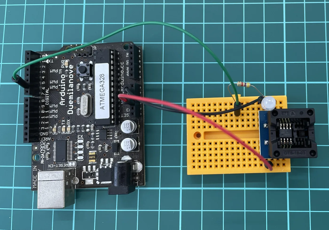
There are two different uploads in this project: first turn an Arduino into a programmer, then upload the application to the ATtiny202. Keeping those targets separate makes setup failures easier to diagnose.
The original setup
The 2024 slides use Windows 11 Pro, Arduino IDE 2.3.2, an Arduino Duemilanove, an ATtiny202, an adapter socket, and a 4.7 kΩ resistor. The Arduino runs jtag2updi and programs the target through UPDI (Unified Program and Debug Interface). Original slides, 3–7.
Separate the five stages
- Upload jtag2updi to the Duemilanove.
- Install megaTinyCore in the Arduino IDE.
- Connect power, common ground, and UPDI. The original jtag2updi setup connects D6 through 4.7 kΩ to UPDI; other programmer designs can use different wiring.
- Select the actual target chip and its settings.
- Use the programmer upload action to transfer the application to the target.
Clarifications to the slides
Slide 8 names ATtiny212 in the Chip field, although the project is about ATtiny202. Match the selected device to the physical part rather than reproducing that inconsistency. In a non-bootloader megaTinyCore configuration, “Burn Bootloader” applies fuse settings; it does not necessarily install a bootloader. megaTinyCore documentation.
The 4 in pinMode(4, OUTPUT) is a logical Arduino pin number, not automatically physical package pin 4. Check the core's pinout. ATtiny202/402 reference.
Find the failing stage
- Arduino upload fails: check the Arduino board selection, port, and programmer sketch.
- Target communication fails: check target power, ground, UPDI, and programmer selection.
- Upload succeeds but no blink: check logical pin mapping, LED polarity, and its current-limiting resistor.
This explains the historical setup. It has not been revalidated with current software and physical hardware.
Related reading and work
For collaborative research, technical validation, or learning-material development, discuss a project.