How to output Arduino's PWM using same timer
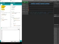
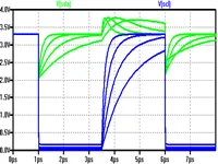
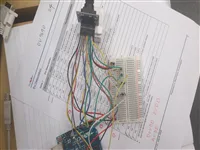
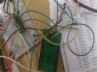
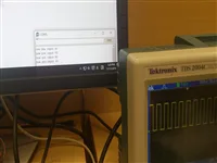
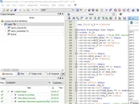
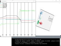
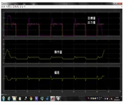
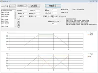
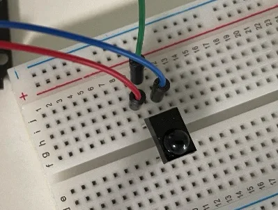
Arduino chip has three timer and each timer can cotrol two pwm pin.
Reference 1 [Arduino Uno – PWM周波数を”自由に”変更する]
Reference 2 [2pin_example.ino]
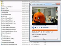
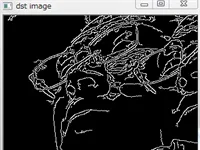
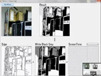
This function is useful if you want to change the image to illustration.
And you are able to do detail coloring because expansion function outputs image path.
2017 / Embedded Systems & IoT
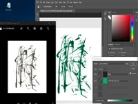
Duotone function in Photoshop
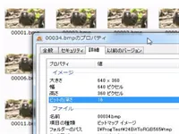
This function is useful if you want to change grayscale to another color.
Especially effective when changing the color of calligraphy.
2017 / Embedded Systems & IoT
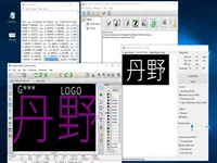
Convert Image to Footprint using KiCad
"Bitmap to Component Converter" function is useful if you want to design logo or antenna on board.
And you can change layer to F.Cu or B.Cu if you rewrite footprint data directly.
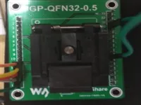
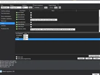
I made ICE40 Writer and confirmed that ICE40 read bitmap from SPI flash memory. Especially, these site are useful.
RelatedWorkConfiguration
2016 / Embedded Systems & IoT
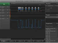
I2C Master using DE0(FPGA)
I made I2C master on FPGA. I evaluated only logic analyzer because I don't have I2C Slave Chip adapted 3.3V or I2C driver.
2016 / Embedded Systems & IoT
PWM Generator using Arduino
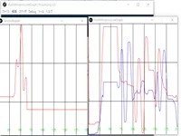
I made it using tone function and analyzing serial read data.
Movie (Youtube)
2016 / Embedded Systems & IoT
Decimal Number Send Using Serial and FPGA
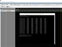
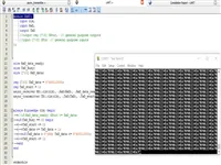
I was successful in implementation of sending decimal 16bit data using serial communication.
Image show decimal value from FPGA on Arduino terminal.
I was successful in implementation of sending decimal 16bit data using serial communication.
Image show decimal value from FPGA on Arduino terminal.
2016 / Embedded Systems & IoT
BCD (Double dabble) Logic Circuit
I was successful in implementation of BCD logic circuit.
First I made it using C# for comparison of data transition. After I made it using MODELSIM.
2016 / Embedded Systems & IoT
Serial Communication Using FPGA
I was successful in implementation of serial communication on FPGA.
I used DE0 board and USB to TTL UART - Serial Converter.
2016 / Embedded Systems & IoT
How to set PWM in Attiny841
115p in 12.12.4 and 116p in Table12-7 on Attiny841 document is useful. only six pin allocate from TOCC0 to TOCC7.
My Memo
2016 / Embedded Systems & IoT
Stabilizer Environment
I made environment and code for stabilizer test using Arduino UNO and MPU6050 and GWSPIC/STD/F GWPIC/STD/F.
Movie(Youtube)
2016 / Embedded Systems & IoT
How to activate pull-up resistor in Attiny841
I found hint in Attiny841 document 57 page. And I realized activate multi PORTA rewriting "PUEA" value.
Dcoument
2016 / Embedded Systems & IoT
SerialAnalogSerial
I made program AnalogRead(ChipA) -> SerialWrite(ChipA) -> SerialRead(ChipB) -> AnalogWrite(ChipB).
Git Code
2016 / Embedded Systems & IoT
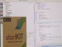
Evaluate XMOS
I confirmed XMOS Start Kit can use AnalogRead (Need XSCOPE set).
This start kit may not helpful because this chip is different from usual chip (chip's resource use writer)
2016 / Embedded Systems & IoT
AtmelStudio
Now version (7.0) can write program to especially chip (e.g. Attiny Series) using only basic install.
Now version (7.0) can write program to especially chip (e.g. Attiny Series) using only basic install.
2016 / Embedded Systems & IoT
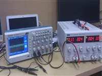
Learn hardware analysis equipment
I used digital oscilloscope and power supply for work.
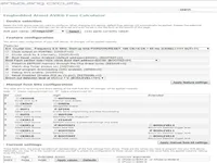
Atmega328p is set as internal clock 8Mhz at default. For same condition as Arduino Uno (Outer 16Mhz), you need to set fuse or burn Arduino.
Fuse EmulatorFuse Reference
2017 / Programming & Software
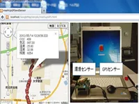
3G Line Communication
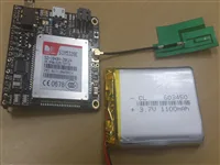
I succeeded sending data using WCDMA (3G Line). I made server using perl for testing.
BandWidthHardATHTTPTCPServer


![How to output Arduino's PWM using same timer
Arduino chip has three timer and each timer can cotrol two pwm pin.
Reference 1 [Arduino Uno – PWM周波数を”自由に”変更する]
Reference 2 [2pin_example.ino]](/images/thumb/2018_09_01.webp)